The Rebuild
Over the past 10 years or so, I have been gathering parts for a total rebuild of the truck. Among those parts are a 392 IHC V8 engine with a T35 five speed transmission and a Brownie 6041 four speed auxiliary transmission. A couple of years ago, I purchased a period correct 36 inch sleeper (see photo below).
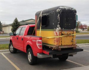
This truck has a lot of interesting sub-stories. In the case of this sleeper, I found it on EBay. It did not sell, but I was able to contact the owner. It turns out that it was located in Kent, WA. I had been doing quite a bit of teaching at Boeing in Auburn, WA. I was able to schedule a driving trip to Boeing in a rented truck. Pat was able to go with me and the trip was a ton of fun, as we got to visit several friends along the way and do a great deal of sightseeing. My only regret was that we did not take a CB radio so that we could hear the truckers discuss our “load”.
In late December 2013, I began the rebuild of this special (to me) truck!!
")

The photos above shows me pulling the original BD 264 six cylinder engine and the trial fit of the IHC 392 V8 engine.
This engine is out of a Loadstar and the only accessory was the alternator. I have gathered the mounting brackets for the IH air conditioning compressor/alternator (passenger side) and the air pump/power steering bracket (driver side). I will be using the IH AC compressor as an on-board air compressor and will be using the air pump bracket as part of a mounting system for a rotary air conditioning compressor for cab air. I will be adding power steering using a Saginaw box (push/pull type) out of a mid ’60s truck.
")
")
")
")
")
IHC engines typically use 3 groove crank pulleys. They offered a special additional groove pulley that can be bolted to the standard pulley. I need the fourth groove for my power steering pump and the AC compressor drive. The auxiliary pulleys are very hard to find and, when found, usually have a damaged outer groove wall. The one I got was damaged. I made a steel ring that I TIG brazed to the damaged pulley and cleaned the groove up in the lathe.
Then I made a set of four “standoffs” for the power steering plate. The one photo shows me turning some steel rod and the second photo shows me drilling the rod. I then cut off 4 pieces about 3/4 inches in length. The standoffs are needed to locate the round PS box to a flat plate. To locate the standoffs on the plate, I made short studs that I threaded into the box and left about 1/2 inch sticking out. The standoffs were place on the studs, and the plate located on the standoffs. Each standoff was then tack welded to the plate.
")
")
 (2)")
")
Next, I began modifying the steering column. In the stock configuration, the column extends to the manual steering box (both the outer tube and the actual steering shaft/tube). For the PS conversion, both the outer tube and inner shaft must be shortened and the system converted to a U-joint based system. One of the pictures in the above gallery shows me turning an oak bushing that will be a part of the steering shaft centering system. The last picture shows several of the components needed to convert the steering column. The Oak bushing is drilled for a bronze bearing in which the steering shaft rotates. The other bronze bushing/plastic bushing is a part of the horn circuit which connects the wire in the steering shaft to the bronze bushing which is insulated from any system ground. Then grounding signal from the horn button will be picked up via an insulated brush holder. I will detail that system in more detail when I fabricate it. In the components photo you can see the parts needed to make a firewall mount for the steering column and a part of the U-joint shaft system that is welded to the inner steering shaft (note that it is cut at an bias to make the weld stronger).
The above photo gallery also shows a couple of photos of the power steering box mounting. The first shows how I reinforced the frame with some temporary steel plate and cut an opening to which the PS plate and permanent reinforcing will be welded. The last picture shows the preliminary assembly of the steering system.
")
I have shown a few pictures of parts I am machining on my lathe. The lathe is a story unto itself. It is a 1918 South Bend lathe with an 18 inch swing, and an 8 foot bed (read HUGE). Many years ago, I swapped an old engine out of my ’47 Buick to a fellow who wanted to get rid of the lathe. To get it running I simply installed a DC variable speed motor controller. I could make parts, but the accuracy and surface finish was not good. Recently, I worked on the spindle. The large bushings that the spindle ride in needed to be cleaned up and re-shimmed. The manual (on-line) says that the clearance should be less than 0.002 inches but more than 0.001 inches. You can measure that with a dial indicator, but the process is clumsy. Instead, I thought I would use a product that measures clearance on engine crankshaft bearings. It is tiny extruded plastic strip that you place on the bearing surface. When you torque the bearing housing, it crushes the plastic strip and you measure how much it spreads. The photo shows that the plastic gage indicates about 0.0015 inches clearance. I did a quick swipe on a piece of cast iron and it looks much better. Considering the age of the technology, I am pleased.
")
")
")
")
Now, back to the truck. My next project was “stretching” the frame 36 inches. A prior owner had shortened the frame and it was just too short. Plus, I want to add the 36 inch sleeper. Through a friend, I found a piece of heavy duty truck frame that was an almost perfect fit to “saddle” the existing frame. My first step was to weld two angle iron frame reinforcements to the frame to keep the frame width stabilized and to act as reference points. I made a 24 inch reference bar to space the reinforcements. In the second photo you see the reference bar along with two additional reference bars that were 36 inches longer. In the third photo you can see the saddle on the frame and the reference bars being used to set the frame length. The last photo shows a close -up of the frame joint. The existing frame was cut perpendicular to the frame, while the saddles were cut at an angle. The angle allows better stress distribution in the welding area and also give about 10 inches of overlap on the frame bottom web for a better fit during installation. Checking the frame by cross measuring indicated that everything was square.


")
The next challenge was building the mounts for the Brownie 4 speed auxiliary transmissions. These transmissions were used from the ’50s through the ’70s to give the operator a large selection of close ratio gears. Today that is done with a integral 9, 10, 13, or 18 speed transmission. Driving one of the old trucks was a real art. There were two shifting levers that had to be “rowed” in a certain order to give smooth acceleration through the gears. I am mainly using the Brownie as an overdrive unit, but I plan to play with the gears a bit when playing like a big truck driver {grin}.
The first photo shows the fit trial of the Brownie. The second photo shows the mounts being fabricate. There will be vibration biscuits at each end of the cross members. I did some looking and found what appears to be a cleaver and cheap way of making the biscuits. Shown is a boat trailer rubber roller. It has a 1/2 inch hole in the center and is about 2.5 inches in diameter. To get the biscuit, you simply cut off a “disk” the thickness you need.
Menu: